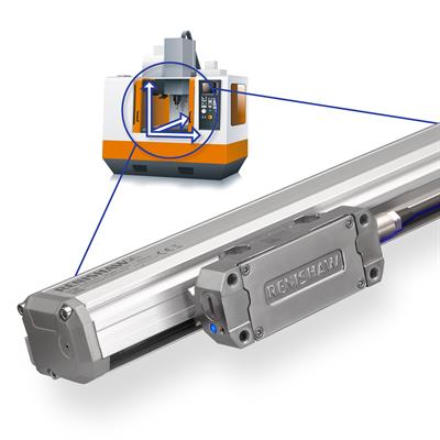
Reducing air purge usage with FORTiS™ encoders, achieving energy saving up to 91%
Using an air purge on linear encoders provides a number of reliability benefits, but generating the required flow of dry, clean compressed air requires a considerable amount of energy over the lifetime of a machine. This has an impact on the total cost of ownership and the lifetime CO2e footprint of the encoders.
Why use an air purge on a linear encoder?
Applying an air purge helps improve the sealing of a linear encoder. If contamination starts to penetrate through the lip seals, the positive pressure in the encoder enclosure helps to push that contamination back out. The air purge is effective against both liquid and particle contaminants.
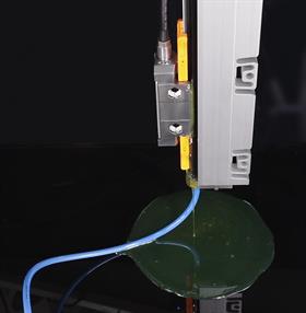 Figure 1: An air purge pumping oil out of a deliberately flooded FORTiS encoder.
It also prevents condensation and ensures that the encoder does not "inhale" dirty air as the enclosure cools when a machine is switched off. This is beneficial throughout the machine's lifetime, especially if the lip seals become accidentally damaged by wear, cuts, or chemical hardening by harsh chemicals inside the coolant.
Furthermore, if contaminants enter the encoder enclosure, an air purge can help pump the contamination back out again. In figure 1, an air purge at 1 bar (0.1MPa) is connected to a FORTiS encoder that has been deliberately flooded with oil.
The air purge is then pumping the oil back out of the encoder, to the point where good signal level has been regained and the encoder is again working properly.
Providing a dry air purge to an encoder that has been flooded with water-based contamination also has a similar effect. These benefits of air purge help to ensure long-term reliability of machines, even under the harshest conditions.
What are the options for an air purge?
Rather than looking at the air purge options as a simple "on" or "off" option, an optimised approach is to match the air purge requirements to the specific axes of a machine.
FORTiS encoders use a unique lip seal material called DuraSeal™. This seals more tightly around the readhead blade, reducing the flow rate of the air purge compared to competitor products. This allows effective sealing to be achieved with a lower air purge pressure.
For axes that are heavily exposed to contamination, especially on machines that are cutting particularly aggressive materials, it is recommended to use the full 1 bar (0.1 MPa) air purge pressure.
However, on many machines the encoders are located in elevated positions, or are relatively remote from the machine chamber. In these circumstances, the encoder will be exposed to significantly less contamination during its lifetime.
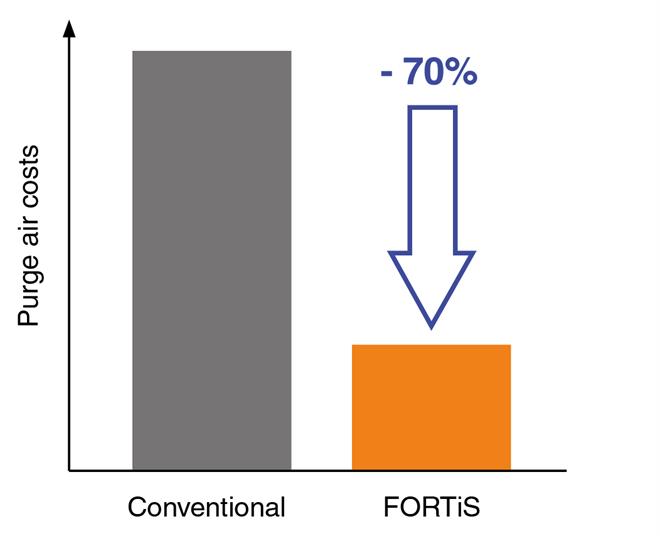
Figure 2 - FORTiS encoders offer reduced air consumption compared to other optical enclosed encoders.
This makes it possible to adopt a low flow air purge philosophy and make savings on air purge usage. Applying a low flow air purge is a simple process. Firstly identify encoders that are good candidates to work at lower pressures. Then simply turn down the pressure on the regulator of the air filter, and check the pressure at the encoders.
What savings can be made?
The tighter sealing of FORTiS encoders reduces the flow rate of the air purge from 7-10 litres/minute to 2 litres/minute. Therefore energy (and CO2e) savings of 70-79% can be achieved just by swapping from a competitor encoder to a FORTiS encoder.
However, by adopting the “low flow” air purge approach, additional savings can be achieved. With 0.5 bar (0.05 MPa) air purge pressure, the savings are increased to 84-89%. When the air purge pressure is turned down to 0.25 bar (0.025 MPa), then savings of 91-94% can be achieved.
| Brand A | Brand B | FORTiS with 1.0 bar air | FORTiS with 0.5 bar air | FORTiS with 0.25 bar air | |
| Encoder power (kWh) | 7.7 | 6.16 | 7 | 7 | 7 |
| Air purge power (kWh) | 446.7 | 312.7 | 89.3 | 44.7 | 22.3 |
Total power (kWh) | 454.4 | 318.8 | 96.3 | 51.7 | 29.3 |
| % reduction vs Brand A | 30% | 79% | 89% | 94% | |
| % reduction vs Brand B | 70% | 84% | 91% |
Notes:
1. This scenario shows the annual power usage. It represents an encoder on a machine that is used for 2 shifts per day, 8 hours per shift, 350 days per year. The air is switched on 24 hours per day, 365 days per year.
2. Encoders are switched on 2 shifts per day, 8 hours per shift, 350 days per year.
3. Encoder power is based on the encoder manufacturer's published data sheet specification for power supply at 5V, multiplied by the annual usage as described in notes 1 and 2.
4. Air purge flow rate of 7-10 litres/minute is based on the manufacturer's published data sheet specification for air purge usage.
5. Air purge power is based on the energy required to provide the annual air usage. This is based on the rate of air flow specified in the manufacturer's published data sheet. This is at a pressure of 1 bar (0.1 MPa), when the air is switched on for 24 hours per day, 365 days per year.
For FORTiS encoders, the annual air usage at a flow rate of 2 litres/minute is 0.002 m3/min x 60 x 24 x 365 = 1051 m3/year. For Brand A, the air purge flow rate is specified in the manufacturer's data sheet at 10 litres/minute. Therefore, the annual air usage is 0.01 m3/min x 60 x 24 x 365 = 5256 m3/year. For Brand B, the air purge flow rate is specified in the manufacturer's data sheet at 7 litres/minute. Therefore, the annual air usage is 0.007 m3/min x 60 x 24 x 365 = 3679 m3/year.
6. To calculate the power required to provide that annual air usage, a representative value of 0.085 kWh/Nm3 has been used. This is a typical value required for an air compressor to provide 1 'Normal cubic metre' of compressed air at 1.0 bar pressure (0.1 MPa) and 15 °C to ISO2533.
When can a "low flow" air purge be used?
Each machine should be evaluated on the level of risk of contamination that the encoders are subject to. The factors that should be considered include:
1. The position of the encoders in the machine.
2. The amount of guarding/sealing between the machine chamber and the encoder location.
3. The type of materials being cut on the machine.
4. The amount of coolant that a specific process requires.
The position of the encoder will have a significant influence on the amount of contamination that the encoder will experience. In general, larger machines expose encoders to less contamination. This is because the encoders are located further from the machining zone.
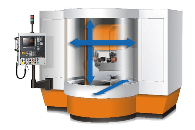
Vertical Machining Centres
In the case of a classic compact vertical machining centre (VMC), the encoders are positioned behind telescoping stainless steel shielding, very close to the machining zone. The shielding does a good job of stopping direct coolant splashes or flying cutting chips/swarf from getting to the encoder. However, over time, contamination will find its way past the shielding, especially particle contamination.
In applications like this, it is not feasible to keep particle contamination away from the encoder, so the encoder must be able to work under those conditions. In these cases, it would be appropriate to apply an air purge pressure of 0.5 to 1 bar (0.05 to 0.1 MPa), with the full 1 bar pressure being applied in cases of machining aggressively abrasive materials. This includes cast iron, ceramics, glass or composites.
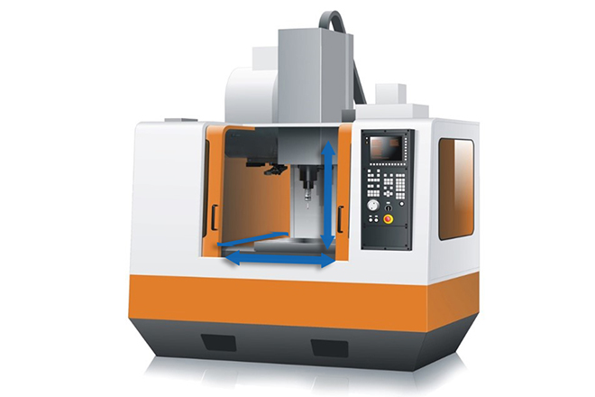
On larger vertical machining centres, the X and Y axes are often located higher in the machine, further from the machining zone. In these cases, it would be appropriate to apply an air purge pressure of 0.25 to 0.5 bar (0.025 to 0.05 MPa) to the encoders.
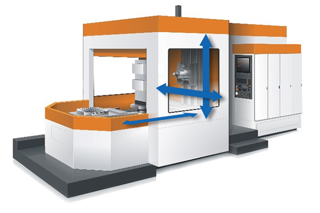
Horizontal Machining Centres
In horizontal machining centres, the appropriate level of air purge pressure is determined by the configuration of the machine. In particular, the Z axis linear encoder may be located under the table where it is difficult to replace and is exposed to larger amounts of contamination. It can also be higher up inside the machine where replacement is easier and the contamination exposure is considerably reduced.
X and Y axes are typically well shielded from contamination, but in some cases the X axis linear encoder can be located under the table.
CNC Tool Grinders
In CNC tool grinding applications, the machine layout is broadly similar to that of a compact VMC. Such applications use large quantities of coolant and the grinding process generates very hard and abrasive particle contamination. In most cases, it is recommended to use the full 1 bar (0.1 MPa) air purge pressure.
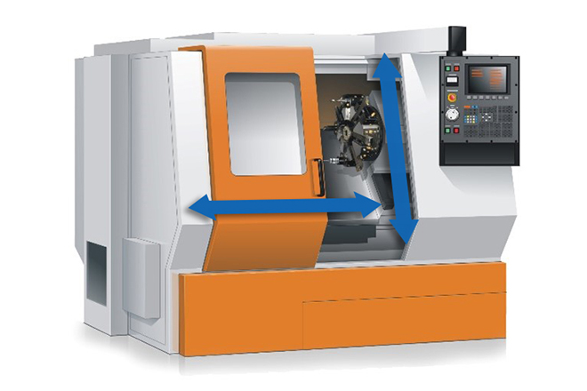
Lathes and Cylindrical Grinders
For lathe and cylindrical grinding applications, the linear encoders are often located close to the machining zone. For most applications an air purge pressure of 0.5 to 1 bar (0.05 to 0.1 MPa) is appropriate. Ease of access to the encoder, the amount of coolant used, and the abrasiveness of the material being machined should be considered when selecting the appropriate air purge pressure.
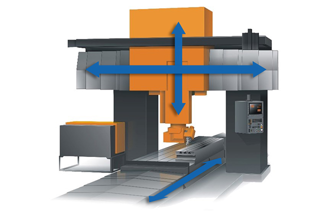
Large machine tools
In larger machines including gantry machines and vertical turning lathes (VTL) the level of contamination experienced by the encoder is typically lower because the linear encoders are mounted further away from the machining zone. In such applications an air purge pressure of 0.25 to 0.5 bar (0.025 to 0.05 MPa) can be used.
Other opportunities for energy savings
Many machines are not used for 24 hours per day, 7 days per week. When they are not being used, the air purge is normally kept switched on to maintain a positive pressure inside the encoder enclosure. This prevents build-up of condensation and stops the "inhaling" effect that occurs when a hot machine cools.
Machines fitted with FORTiS encoders can overcome both of these effects with the air purge turned down to 0.25 bar (0.025 MPa) pressure overnight, at weekends, or during factory shutdowns.
For some machines, most linear encoder axes are well protected from contamination. However, there may be one linear encoder axis that is at higher risk. In a situation like this, an additional regulator can be fitted to the air filter set. This will allow air to be fed to the higher risk encoder at 1 bar (0.1 MPa) while the lower risk encoders can be supplied with an air purge at lower pressure.
Summary
The superior sealing performance of the FORTiS enclosed linear encoder enables an optimised approach to providing air purge to the encoders on a machine.
This "low flow" approach can deliver significant benefits of reduced compressed air consumption, leading to lower associated energy costs. This also maintains the long-term reliability benefits of using air purge systems.
Linear encoders are fitted to a wide range of CNC machines, and there are many variations of each machine type. Interested parties are invited to speak to a Renishaw expert about their particular application.
Contact our sales team today
Get in contact with your local office to find out more information and speak to an expert.